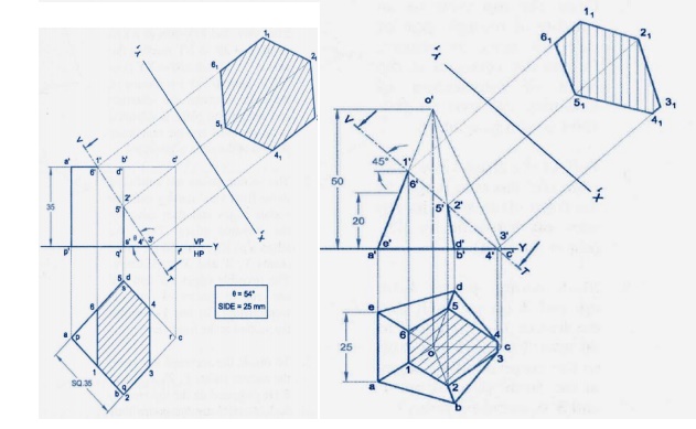
School Indian Institute of Technology Tirupati. Draw X 1Y 1 line inclined at q the inclination of AIP with HP to XY line.

Projection Of Solids Problem 1 In Autocad Youtube
Standard exceptions are noted previously.
. Face Rectangular Top a Triangular prism Base c Rectangular prism Edge Axis d Pentagonal prism b Square. Ad Extract Measures Tolerances from engineering drawings. 1Draw proper outline of new vie project its Tv below xy.
Hence let us first locate the points of intersection in that view. Draw the projectors through Draw the projectors through the Step by step procedure to draw auxiliary views the top viewsof the points perpendicular to the X 1Y 1 line. Get Free Engineering Graphics Projection Of Solids Engineering Graphics Projection Of Solids Projection of Solids_Problem 1 in AUTOCAD Projections of solids - Hexagonal prism Engineering drawing 2014 Dec 5a Projections of Solids 13a exercise solutions Engineering drawing by NDbhatt textbook PROJECTION OF SOLIDS ENGINEERING GRAPHICS SUBJECT.
It may be completed. We support PDF PNG TIFF more. Steigern Sie Ihre Produktivität.
Ad Extract Measures Tolerances from engineering drawings. Download full-text PDF Read full-text Figures 7 Abstract and Figures This book includes practice problems for Engineering Drawing course. Solids generally used in the study of Engineering Drawing may be classified as.
Assume that the length of both the prisms is 100 mm. 2 A vertical square prism base 50 mm side and height 90 mm has a face inclined at 30Oto the VP. 1 line inclined at f the inclination of AVP with VP to the XYline.
Engineering drawing 1st year projection of solids fplusm de. Engineering drawing 1st year projection of solids hcinfo de. Ad Die Zukunft in der CAD-Konstruktion.
Content uploaded by Mahesh Chandra Luintel. The isometric projection of all other. View Projection of solidspdf from ME 1480 at Indian Institute of Technology Chennai.
Engineering graphics pdf notes handout amp ebook for first. The figure shows the layout of a typical sheet showing the drawing frame a. Steigern Sie Ihre Produktivität.
Bhatt INTERSECTION OF PRISM AND PRISM Prob. 2008 12 McGraw-Hill Education. Figure T26 Figure T25 10 Figure T45 Figure T62 a.
Projection Of Solids Engineering Graphics and Engineering Drawing Orthographic projection - Engineering drawing - Technical drawing Orthographic Projection - Engineering drawing - Technical drawing Problem no7 Projection of lines in sketch CDT G1011 - First Angle Orthographic Projection Part 1 Whats the difference between First Angle u0026. Projection of Solids Engineering Drawing Anup Ghosh Department of Aerospace Engineering Indian Institute of Technology Kharagpur August 29 2011. Projection of Solids Naming convention 1 All visible points are marked out side the drawing 2 All hidden points and marked inside the drawing.
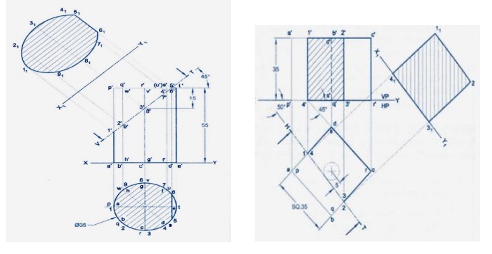
Section plane parallel to HP. 6Make visible lines dark and hidden dotted 2. Procedure 2 1Diameter of the circle in true view is ag.
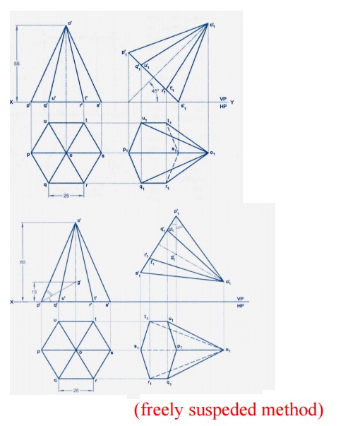
Lecture 08_Projection of solidspdf - Engineering Drawing PROJECTIONS OF SOLIDS u2013 IL08A man is not finished when he is defeated He is finished when. Select nearest point to observer 7Then construct remaining inclination with Vp and draw all lines starting from generator o1e1 300 to xy as shown project final Fv. Access the Measures Tolerances GDTs in your Enginering Drawings with one API call.
Lecture 08_Projection of solidspdf - Engineering Drawing. Draw the projection of the solid without section plane. Section plane A section.
Carry it to the front view. Engineering Drawing Course Code. Top view and front view according to the given conditions.
Decide direction of an observer. Ad Die Zukunft in der CAD-Konstruktion. A sectional view must not have any full lines drawn over hatched areas.
Draw the projections of the solids showing lines of intersection. Then introduce the section plane in the top view. Anup Ghosh Engineering Drawing Projection of Solid Section Projection of truncated sphere Procedure 1 1Let us assume a horizontal plane passing through c 2Cut on the vertical projector point c with center o with a radius of the horizontal plane.
MENG 204 - Mechanical Drawing Lecture Notes by. Engineering drawing 1st year projection of. Pages 27 This preview shows page 1 - 11.
This book includes practice problems for Engineering Drawing course. As it is parallel to the VP is seen as a line in top view. Ist year engineering graphics ed for be students 1 1.
Course Title ED NARAYANA. In thirdangle projection the sectional view is placed on the side behind the sectioning viewing plane. Isometric Projection of Solids Isometric View of Solids Isometric Projection 1Isometric means equal measure 2mutually perpendicular plane surfaces of an object and the edges formed by these surfaces are equally inclined to a plane of projection 3only one view on a plane is drawn to represent the three dimensions of an object.
Draw the projections of the prisms showing lines of intersection. A solid may be defined as an object having dimensions like length breadth and thickness. Abstract and Figures.
The faces of the vertical prism are seen as lines in the top view. Engineering Drawing Lecture 10 29082011 1 Projection of Solids Indian Institute of Technology Guwahati Guwahati 781039 Solids A 3-D object having length breadth and thickness and bounded by surfaces which may be either plane or curved or combination of the two. Keywords Solid Diagonals Slanted Edge Invisible Edges Side Elevation Angular Points.
Engineering Drawing Projection of solids Images in this presentation have been taken from Engineering Drawing by. Questions amp answers engineering graphics. Anup Ghosh Engineering Drawing.
Material which has been cut by the cutting plane is hatched. A text book on engineering graphics central board of. So for drawing the first view keep.
Assume suitable lengths for the prisms prisms in the required position. Access the Measures Tolerances GDTs in your Enginering Drawings with one API call. As per the procedure.
Face a Tetrahedron c Octahedron d Dodecahedron b Cube e Icosahedron. Ala Hijazi Engineering Working Drawings Basics Page 2 of 22 Drawing Sheet Layout Standard layouts of drawing sheets are specified by the various standards organizations. Classified under two main headings Polyhedron Solids of revolution.
We support PDF PNG TIFF more. 170 mm 235 mm Binding.

Pdf Practice Problems For Engineering Drawing I
Projection Of Solids And Section Of Solids

3 Textbook Of Engineering Drawing Pages 151 200 Flip Pdf Download Fliphtml5

Engineering Drawing With Annotations Of A Physical Object In Third Download Scientific Diagram
Projection Of Solids And Section Of Solids
Projection Of Solids And Section Of Solids

Computer Aided Engineering Drawing 20me12p Unit 02 Part 04 Projectio

Projection Of Solids Problem 1 In Autocad Youtube
0 comments
Post a Comment